
How Can We Help?
SU series CPU replacement (KPP)

Question
I would like to update the SU series CPU.
Which is the successor model?
Will it work if I replace the memory cartridge?

Answer
The successor model of SU series CPU is D4-454.
However, some old I / O modules do not work, so please check the I / O module you are using.
In addition, since the structure does not use a memory cartridge, use a programmer such as S-01P2 or Koyo PLC Programming Software to copy the program and system parameters.
-Note-
*Modules U-01AD,F4-04DA,U-04AD-1,U-4SCA-1,U-11DN,U-01SA.U-01NI(DA-INT),U-03RM(D4-AM),U-03RS-xxxx(D4-SS-xxxx),U-01KF/U-01KI,H4-ECOM,and H4-ERM are not supported.
*Port3 has only DSUB25P connector.
Replacement procedure
Equipment
Read the ladder program of the existing CPU
1. Start up your computer and connect the communication cable to the CPU before the change (existing).
For the connection method, please see here.
2. Start KPP.
3. Read the ladder program from the PLC.
For the reading method, see here.
For the connection method, please see here.
2. Start KPP.
3. Read the ladder program from the PLC.
For the reading method, see here.
Check the scan time of the existing CPU
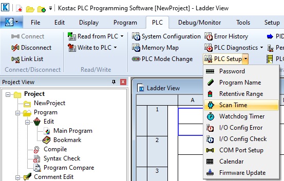
4. Select Scan Time (T) from the diagnostics in the PLC menu.
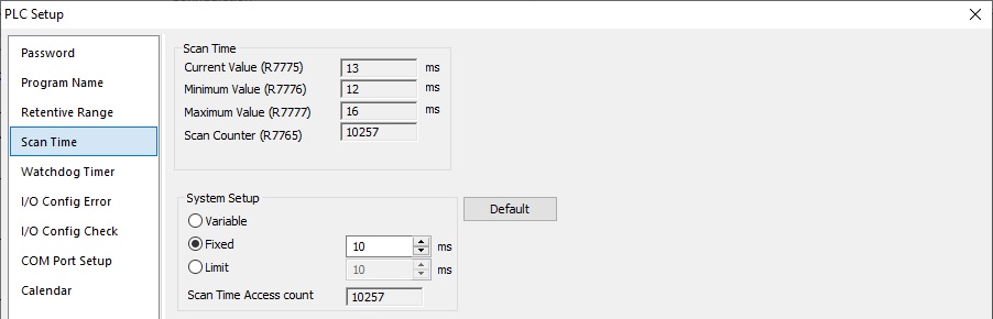
5. Make a note of the scan time of the existing CPU displayed.
6. Press the End button to close the scan time display.
5. Make a note of the scan time of the existing CPU displayed.
6. Press the End button to close the scan time display.
Save ladder program
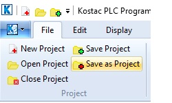
7. Select Save As from the File menu.
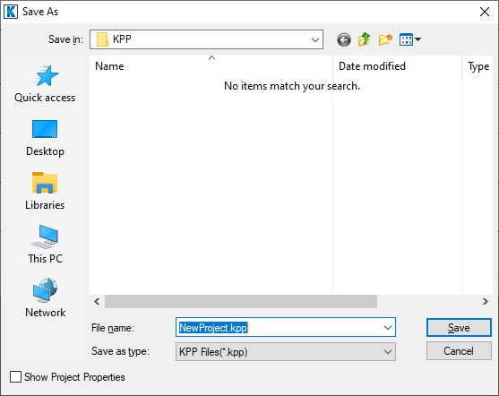
8. Select any folder, enter the file name and press the Save button.
After saving as, disconnect the CPU.
By saving as a name, registers, bit information and CPU setting information are saved.
After disconnecting, display the displayed ladder circuit screen without erasing it.
8. Select any folder, enter the file name and press the Save button.
After saving as, disconnect the CPU.
By saving as a name, registers, bit information and CPU setting information are saved.
After disconnecting, display the displayed ladder circuit screen without erasing it.
CPU module replacement
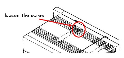
9. Turn off the power of the control panel, open the CPU front case, disconnect the wiring of the power supply, and loosen the fixing screw on the top of the CPU.
10. Hook the tab on the bottom of the CPU to be replaced on the stopper under the base, push it into the base, and tighten the screw on the top.
Write the read ladder program to the replaced CPU
11. Attach the communication cable to the replaced CPU and turn on the power of the control panel.
12. Connect the open KPP to the replaced CPU
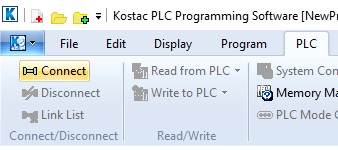
Select “Connect” to launch the registered communication link screen.
If the communication link for the CPU to be replaced is not registered, press the new button to create a new communication link.
If you have already registered, select that communication link.
13. The following message is displayed because there is a difference between the replaced CPU and the running KPP.
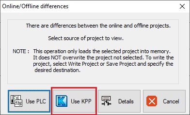
Select Use KPP Disk on the above screen.
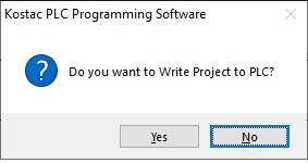
14. Select Write All from Write to PLC in the PLC menu of KPP.
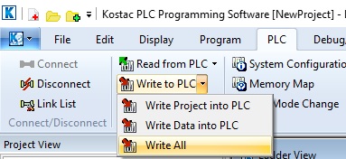
A write confirmation message is displayed.
Select “Yes”.
After the program transfer, it changes to parameter transfer.
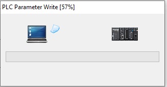
If you select batch write, the program and system parameters will be transferred.
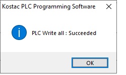
After the transfer is completed, the following display will be displayed. Now press the OK button.
15. Download the project and check the operation of the device.
If there is a problem with the operation, check the scan time of the CPU after replacement by the methods 3 and 4 above.
16. Select the scan time from the PLC settings.
Check the CPU scan time after replacement
17. Select “Fixed” from the scan control menu, enter the CPU elapsed value, and then replace.
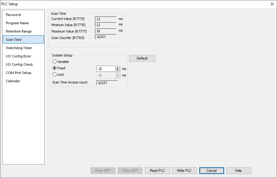
* When fixed scan is set, the minimum value is 10 msec.
18. After setting, press the “Write PLC” button at the bottom of the PLC setting screen.
caution:
After setting the scan control to “Fixed scan”, if you change or add a user program, the scan time may change.
If the change shortens the scan time, there is no problem. (It will operate at the fixed value.)
Depending on the changes, the scan time may become longer than the fixed value.
In this case, special relay: SP37 turns on, and the number of times is counted in special register: R732.
Reference information
The general-purpose communication port (D-Sub25pin) of SU-5, 5E, 6, and 6B is Port1.
When connecting to the corresponding CPU and backing up the parameter to DL454, a communication error may occur due to the difference in data holding.
Therefore, be sure to reconfigure and write the communication settings using KPP.
* The pin assignment of RS-232C / 422 of the general-purpose communication port of SU-5 / 5E / 6 / 6B is the same as that of Port1 of SU-5M / 6M, DL450 and DL454.
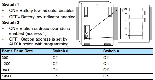
With / without battery setting
The settings for SU-5, 5E, 6, and 6B with / without batteries are set with the DIP switch on the back of the CPU.
Check the DIP switch on the back side of the corresponding CPU and reflect that information in Bit12 of register R7633.
Register R7645 Bit12
ON: Mode with battery
OFF: Battery-free mode
Check the DIP switch on the back side of the corresponding CPU and reflect that information in Bit12 of register R7633.
Register R7645 Bit12
ON: Mode with battery
OFF: Battery-free mode
Related keywords
SU-5 SU-5E SU-5M SU-6 SU-6B SU-6M SU-6H
Inquiry
Technical support
Click here for inquiries by email
Click here for inquiries by email