
JX-CAM
Programmable Cam: Easy replacement of FC2 seriesavailable from October 2025
Programmable cam specialized in angle detection
A programmable cam is an electronic cam that detect angles using an absolute encoder instead of mechanical cam control and switches the output ON/OFF according to the preset angles.
We offer products that can serve as replacements for the OMRON Cam Positioner H8PS.
Please contact us for further details.
Feature
- Two Models available according to control scale
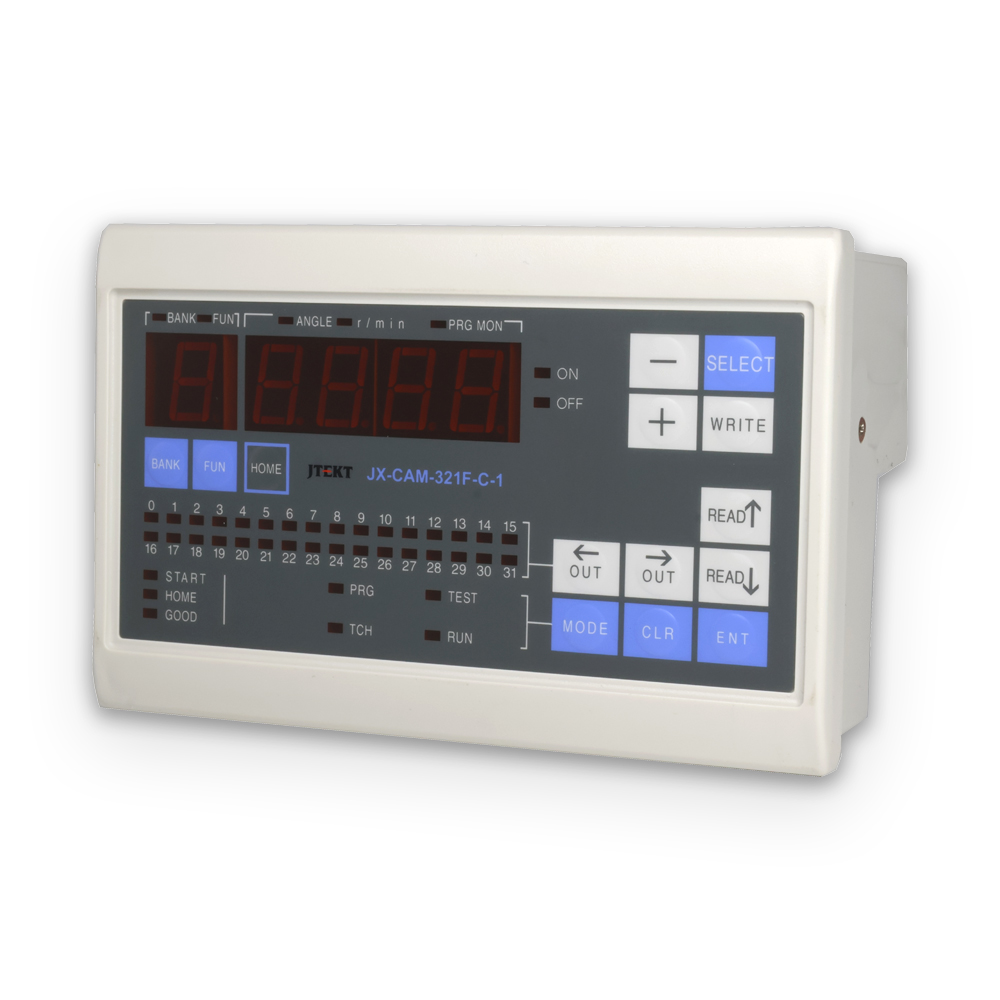
16 Output Points: JX-CAM-161F-C-1
32 Output Points: JX-CAM-321F-C-1 - Easy setup change
Up to 10 program banks can be registered.
Any program can be selected using bank input. - Fine adjustment of ON/OFF output angles during operation
In TEST mode, the ON/OFF output angles can be finely adjusted without stopping the machine. - External origin setting capability
During programming, the origin (0°) can be set to any angle via PC Configuration Tool or key operations. - Equipped with convenient special features
- Pulse output setting function
In addition to setting ON/OFF output within a range of rotation angles, the pulse output setting function allows specifying how many pulses are output per rotation (division output). - Advance angle function
Automatically compensates for mechanical response delays proportional to the rotation speed. - Copy function
Allows saving, loading and verifying programs between programmable cams or internal banks. - Protection setting function
Allows detailed protection settings for output configurations.
- Pulse output setting function
- Communication function
Equipped with an RS-232C communication port for configuration and operation monitoring via PC or PLC (programmable logic controller). - Migration of FC2 series settings data
By using the “Programmable Cam Workbench” configuration tool, programs from the FC2 series can be migrated to the corresponding JX-CAM series product
Specification
Product Specifications
| Items | Specifications | |
|---|---|---|
| Model Number | JX-CAM-161F-C-1 | JX-CAM-321F-C-1 |
| Power Supply | DC12/24V | |
| Voltage Fluctuation Range | DC10.8 ~26.4V Ripple 3%rms | |
| Power Consumption | 8W | |
| Operating Temperature | -10 ~ 50℃ | |
| Storage Temperature | -20 ~ 70℃ | |
| Operating/Storage Humidity | 35 ~ 85% RH (No condensation) | |
| Operating Atmosphere | No corrosive gases | |
| Insulation Withstand Voltage | Not specified, as DC power input and input/output are not insulated | |
| Insulation Resistance | Not specified, as DC power input and input/output are not insulated | |
| Vibration Resistance | Durability: Displacement amplitude 0.5mm, 10~55Hz, 3 times in 3-axis directions | |
| Malfunction: Displacement amplitude 0.35mm, 10~55Hz, 3 times in 3-axis directions | ||
| Complies with JIS C0911 | ||
| Shock Resistance | Durability: 500m/s2 (50G), 3 times in 3-axis directions | |
| Malfunction: 100m/s2 (10G), 3 times in 3-axis directions | ||
| Complies with JIS C0912 | ||
| Noise Resistance | Between Power Supply Terminals: 1.0kV | |
| Pulse Width: 1μs/Start-up 1ns/Square wave pulse | ||
| (Tested using a noise tester) | ||
| Protection Rating | IP54 (Front Sheet Only) | |
| Size | 140×90×60.5(mm) *When not connected to a rotary encoder | |
| Panel Cut Dimensions | 135×85(mm) | |
| Weight | About 420g | |
Functions/Performance
| Items | Specifications | ||||||||||||||||||
|---|---|---|---|---|---|---|---|---|---|---|---|---|---|---|---|---|---|---|---|
| Model Number | JX-CAM-161F-C-1 | JX-CAM-321F-C-1 | |||||||||||||||||
| Control Inputs | Power Supply: DC12/24V | ||||||||||||||||||
| Logic ON Voltage: 0~2V(Low) OFF Voltage: 7.5~30V(High) | |||||||||||||||||||
| Start Input: 1 point | |||||||||||||||||||
| Protection Input: 1 point | |||||||||||||||||||
| External Origin Input: 1 point | |||||||||||||||||||
| Bank Input: 4 point | |||||||||||||||||||
| Rotary Encoder Input | Open Collector Output: Withstands voltage above 14V | ||||||||||||||||||
| Logic ON Voltage: 0~1.5V(Low) OFF Voltage: 4~5V(High) | |||||||||||||||||||
| Resolution: 32/64/128/180/256/360/512/720/1024(Output Code: Gray Binary) | |||||||||||||||||||
| Output Specifications | NPN Open Collector: Withstands voltage below 35V / Current below 0.1A | ||||||||||||||||||
| Output Points *1 | 16 points | 32 points | |||||||||||||||||
| Number of Output Area Settings *2 | 128 points | ||||||||||||||||||
| Angle Setting Unit | Resolution | 180 | 360 | 720 | 32 | 64 | 128 | 256 | 512 | 1024 | |||||||||
| Setting Unit | 2° | 1° | 0.5° | 0.1° *3, or 1 resolution step | |||||||||||||||
| Response Rotational Speed *4 | Resolution | 32 | 64 | 128 | 180 | 256 | 360 | 512 | 720 | 1024 | |||||||||
| rpm | 50000 | 26000 | 13000 | 10000 | 6800 | 5000 | 3200 | 2500 | 1600 | ||||||||||
| Output Response Time | ≤ 30 μs | ||||||||||||||||||
| Power Startup Time *5 | ≤ 2s | ||||||||||||||||||
| Number of Banks | 10 | ||||||||||||||||||
| Program Memory *6 | EEPROM | ||||||||||||||||||
| Resolution Switching | 360/720: Switch via DIP switch | ||||||||||||||||||
| CW/CCW Switching | Switchable via DIP switch | ||||||||||||||||||
| RUN Output | Turns ON during normal operation in RUN/Adjustment mode (configurable via DIP switch). | ||||||||||||||||||
| OUT15 | OUT31 | ||||||||||||||||||
| Rotation Speed Alarm Output *7 | Rotation speed alarm output: Activates when the actual speed is outside the set upper or lower limit range (configurable via PC Configuration Tool). | ||||||||||||||||||
| Upper Limit Alarm:OUT14 Lower Limit Alarm:OUT15 | Upper Limit Alarm:OUT30 Lower Limit Alarm:OUT31 | ||||||||||||||||||
| Display Switching | Angle/Rotation Speed: Switchable via DIP switch | ||||||||||||||||||
| Origin Correction | Allows setting any position as the origin (using key operation, external origin input, or communication write). | ||||||||||||||||||
| Special Features | Advance Angle Function | Adjusts output points proportionally to the rotary encoder’s speed to compensate for machine transmission delays. | |||||||||||||||||
| Pulse Output Function | Sets the number of square wave pulses output by the rotary encoder per rotation, supporting pulse output for all points. | ||||||||||||||||||
| Copy Function | Copies and transfers configuration parameters. | ||||||||||||||||||
| Protect Setting Function | Prevents incorrect operations by disallowing overwriting of configuration parameters. | ||||||||||||||||||
| Communication Function | RS-232C (Connector: RJ-12, Protocol: Modbus/RTU). | ||||||||||||||||||
| Accessories | Mounting Brackets | ||||||||||||||||||
*1: Connector type
*2: Number of configurable settings per bank
*3: There may be slight deviations in angle detection.
*4: This is the theoretical speed at which the programmable cam operates correctly. Actual speed may vary depending on the response frequency of the rotary encoder.
*5: Time from power-on to output ON when the startup input is ON.
*6: Rewrite endurance: approximately 1,000,000 cycles
*7: Settings are configured individually for each bank.
Technical manual, Software, CAD data
Information of Model Numbers
Programable Cam
| Model Numbers | Overview |
|---|---|
| JX-CAM-161F-C-1 | Programmable Cam JX-CAM (16 Output Points) |
| JX-CAM-321F-C-1 | Programmable Cam JX-CAM (32 Output Points) |
Usable Rotary Encoder
| Model Numbers | Overview |
|---|---|
| TRD-NA360NWF2 | Resolution:360 Cable Length:2m |
| TRD-NA360NWF2-5M | Resolution:360 Cable Length:5m |
| TRD-NA720NWF2 | Resolution:720 Cable Length:2m |
| TRD-NA720NWF2-5M | Resolution:720 Cable Length:5m |
Inquiries Concerning Products
Please wait for a while until form appears.
Please contact us, if form does not appear even in some time later.