
Handshake the operation and completion of PR mode

Question
I heard that the JTEKT Electronics servo system can operate the motor without a PLC motion controller by using PR mode.
I would like to instruct which PR to execute using DO from the PLC, receive information on whether the command has been executed via the PLC’s DI, and then perform a handshake.
What should I do?

Answer
Set the servo system to “PR mode” using the AC servo system setting software: KSD-Soft.
By registering the servo motor operation settings in a program and outputting DO from the PLC, the motor can be operated.
Furthermore, the DO of the servo system is controlled by the PR mode program and is used as a feedback signal to the PLC.
Please refer to the following for the setting procedure.
Setup Steps
Connect the computer and AC servo system using the dedicated USB cable.
Start the configuration software: KSD-Soft and connect the AC servo driver via USB.
1. Reading parameters
Start the “Parameter Editor” and click “Read Parameter” from the icon to read the servo driver parameters.
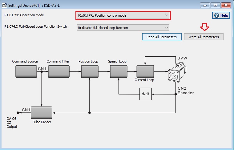
2. Set the operation mode to “PR mode”
Start the “Mode Setting” and set the operation mode to “[0x01]PR: Position control mode”.
To enable the settings, turn the servo system power off -> on.
* If you turn the servo system power off -> on, KSD-Soft will go offline, so please reconnect.
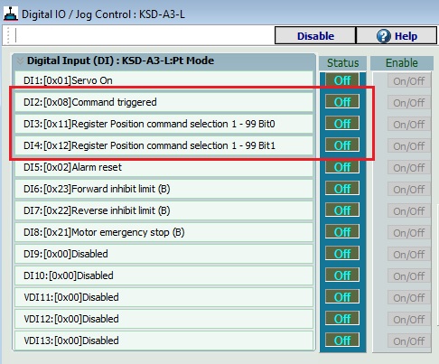
3. Digital Iuput Setting
Click “Digital DIO / JOG control” of KDS-SOFT.
Since we want to control bits from an external PLC, we assign “Command triggered” and “Register position command selection Bit0, Bit1” to DI.
* In this example, we want to be able to specify programs 1 and 2, so we will register Bits 0 and 1.
* If there are many program patterns, increase Bit2,3, etc. as necessary.
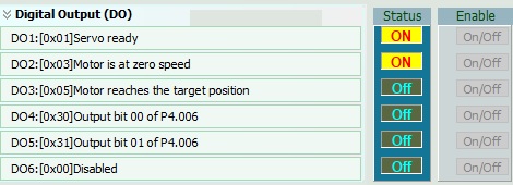
4. Digital Output Setting
Since we want to output the execution status of PR mode to the external PLC in bits, we set DO to “soft control”.
* In this example, we want to be able to specify programs 1 and 2, so we will register Bits 0 and 1.
* If there are many program patterns, increase Bit2,3, etc. as necessary.
5. Register the program to the servo driver
99 programs can be specified for the servo driver, and the program to be executed from the PLC can be specified by turning on/off the “Register Position command selection bitX” assigned to DI.
In this example, the operation of programs #1 (PR #1) and #2 (PR #2) will be instructed from the PLC.
Then, to perform feedback processing, the actual operation is registered in programs #11 (PR #11) to #16 (PR #16).
6. Receiving instructions from PLC
Activate PR mode settings and select PR #1.
Tells you to jump to PR #11.
(Similarly, PR #2 should jump to PR #14)
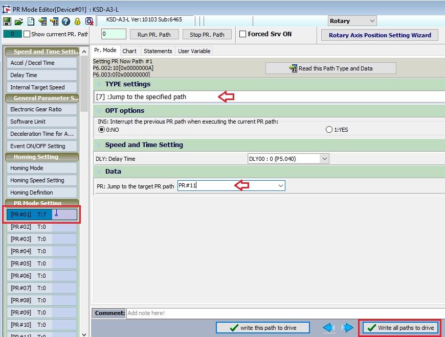
7. Operation settings
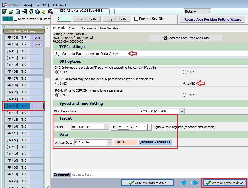
In PR #11, set all feedback DOs to OFF and jump to the next PR#. (Same as PR #14)
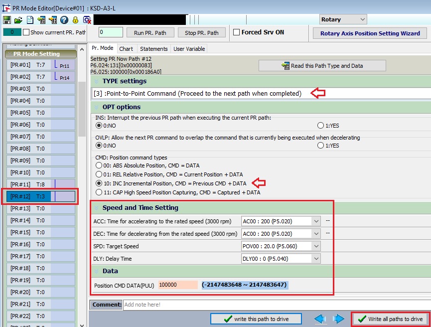
Set the operation program to rotate the motor forward in PR #12.
Once the action is complete, set it to jump to PR #13. (Reverse operation is registered in PR #15)
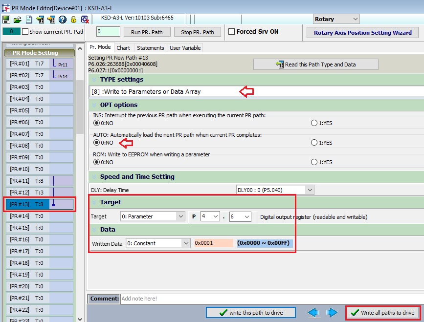
PR #13 is set to output DO for feedback. (Same as PR #16)
PR #1 Once execution is complete, set DO4 On, DO5 Off. (DO4 Off, DO5 On in PR #16)
8. Driving
Turn on the servo.
If you turn DI4 on, DI5 off, and DI3 on, forward rotation will occur.
(DI3 will be turned off once)
When the forward rotation operation is completed, DO4:On DO5:Off.
Next, turn DI4 Off, DI5 On, and turn DI3 On to perform reverse operation.
(DI3 will be turned off once)
When the reverse operation is completed, DO4:Off and DO5:On.
9. To be more certain
Assign “0x05: Moter reaches the target position” to DO and look at this signal with an AND condition.
Inquiry
Click here for inquiries by email