
FG-01 replacement

Question
I am using FG-01, but I heard that it is discontinued.
If there is an alternative, please let me know.

Answer
Can be replaced with PLC:SJ-ETHER if used under the following conditions:
– CW/CCW count output is not used.
– DC output is not used.
For specific details, please see “Replacement procedure” below.
Replacement procedure
System configuration and wiring diagram
The difference between the two products is the difference in supported networks.
Click here for details.
Change the wiring of FG-01 as shown in the figure below.
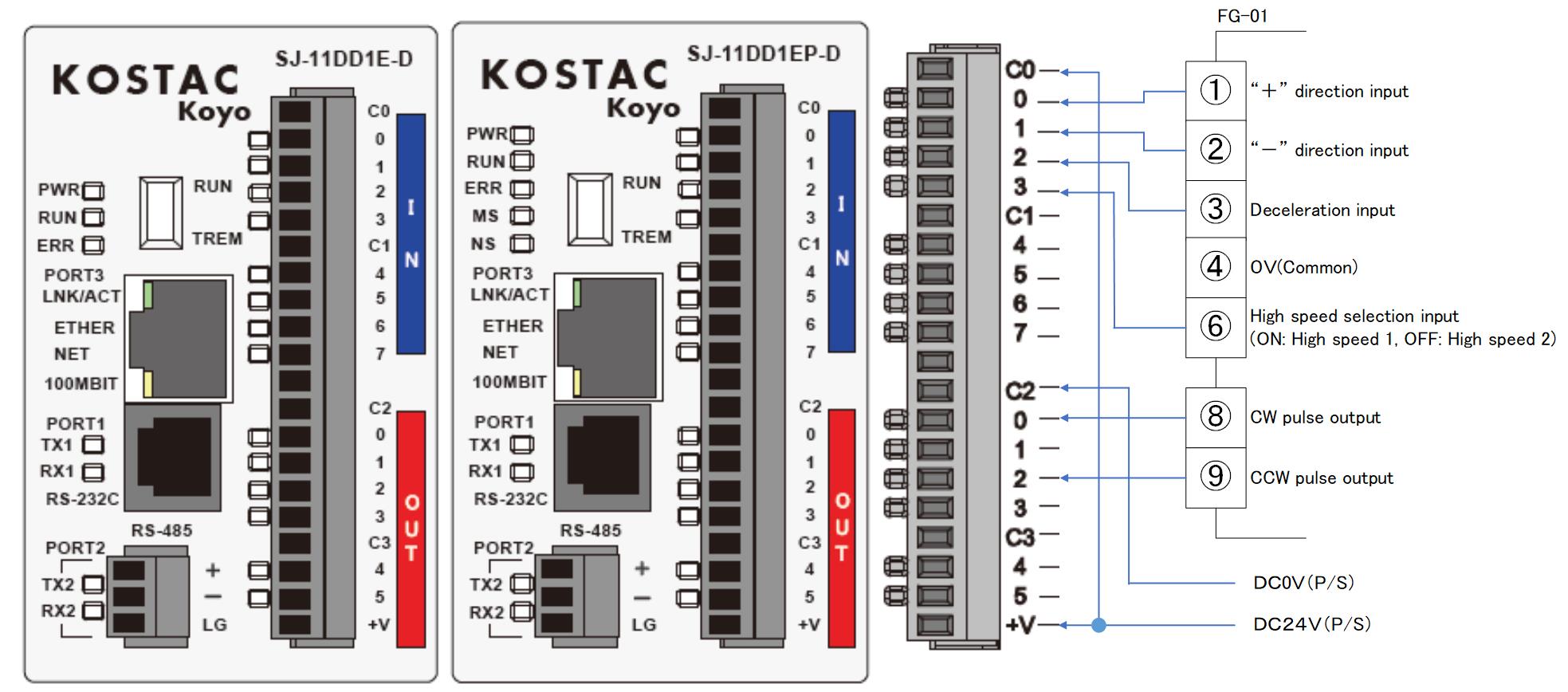
The PLC power supply is DC24V. You can also use our product: C0-01AC.
* SJ-ETHER pulse output is NPN open collector.
When connecting a counter, connect it to the counting input (negative logic) of the counter in parallel with the motor driver.
SJ-ETHER sample program
The addresses of the data registers used are as follows.
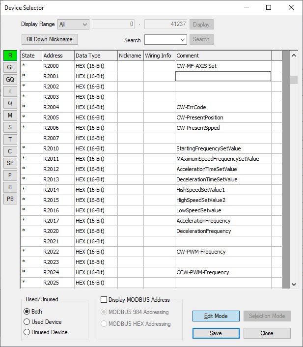
Starting frequency
Used when using a pulse motor.
It will be set to accelerate from this frequency at startup.
If set to 0, a loss will occur during acceleration.
Please set it to 0 when using a servo motor.
Maximum speed frequency
Match the motor driver specifications.
An overview of system operation
1.When the “+”” direction input (I00) is turned ON, calculations are performed according to the starting frequency setting value, maximum speed frequency setting value, and acceleration time setting value, and the SJ-ETHER timer interrupt with a cycle of 1ms is activated, and the 1st axis of PWM pulse output ( Output starts from Q00).
2.Add acceleration frequency for each timer interrupt.
3.When the high speed 1 or high speed 2 setting value is reached, acceleration is stopped and pulse output at the frequency of the high speed setting value is continued.
4.When the deceleration input (I02) turns ON, subtract the deceleration frequency for each timer interrupt.
5.Stop deceleration when the deceleration setting value is reached.
6.The same operation as above occurs for “-“direction input (I01). PWM pulse output is output from the second axis (Q02).
Inquiry
Click here for inquiries by email