
Rotary axis position command (Index Control)

Question
I would like to control the position of a servo motor by specifying an angle.
Is there a better way?

Answer
This can be easily done using the “Rotary/Axis Position Setting” in PR mode.
As examples, we will explain the following three cases.
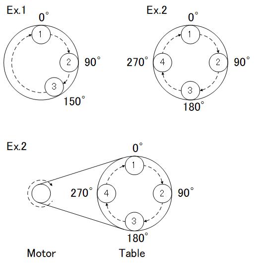
| Case study | Content |
|---|---|
| Ex.1 | When moving to 0 -> 90 -> 150 (degree) positions |
| 例2 | hen moving to 0 -> 90 -> 180 -> 270 (degree) positions |
| Ex.3 | When moving a shaft connected to the motor shaft with a pulley to positions of 0 -> 90 -> 180 -> 270 (degree) * Explanation is based on reduction ratio: 1/5. |
* In either case, the denominator of the E-Gear ratio will be explained as “360000”.
Setup steps
1. Mode Setting
Set the Operation Mode to “[0x01]: PR Position control mode”.
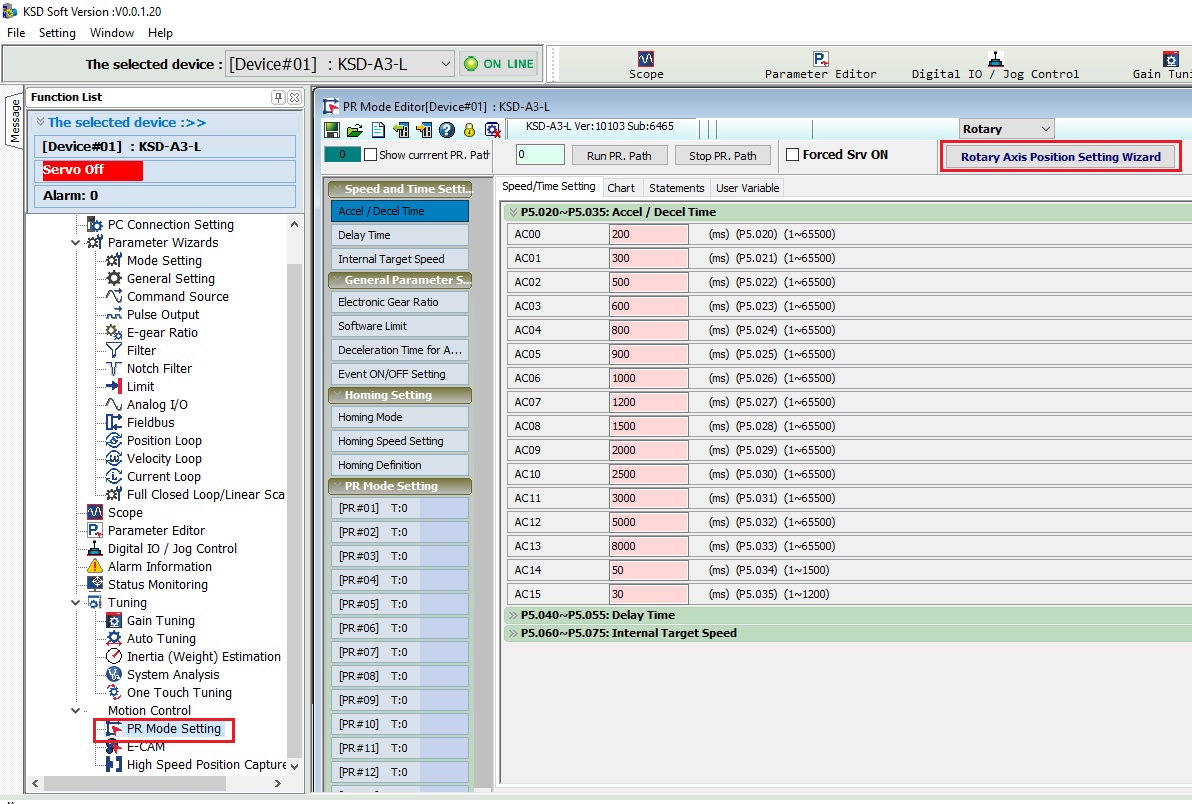
2. Rotay/Axis Position Setting Wizard
Click “PR Mode Settings” from KSD-Soft.
Then click “Rotay/Axis Position Setting Wizard”.
Set the Knife numbers, Rotary axis position scale, rotation direction, etc.
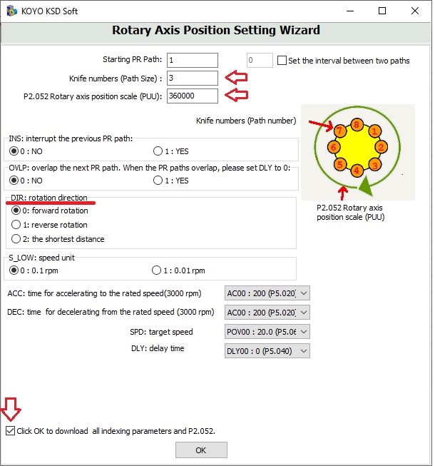
Knife number
| Knife number | Specify the number of positions you want to stop at |
|---|---|
| ex.1 | Since I want to specify three positions, I set it to “3”. |
| Ex.2, EX.3 | Since I want to specify 4 positions, I set it to “4”. |
Rotary axis position scale
| Rotary axis position scale | Position data required when making one revolution (PUU) |
|---|---|
| Ex.1, Ex.2 | Since the denominator of the E-gear ratio is 360000, the PUU for one revolution is 360000. |
| Ex.3 | To make the right shaft go around once, the motor shaft must rotate 5 times. (Since the reduction ratio is 1/5) Thus, 360000 x 5 = 1800000. |
“Check” the checkbox indicated by the downward arrow and click “OK”.
3. Adjustment of stop coordinate position
The coordinate position divides the index coordinate Rotary axis position scale equally by the number of passes.
In Ex.2 and Ex.3, the angle is controlled at equal intervals, so no adjustment is necessary.
In the case of Ex.1, since the intervals are not equal, change the position data of PR #2 and PR #3.
PR #2: Changed to 90000 PR #3: Changed to 150000
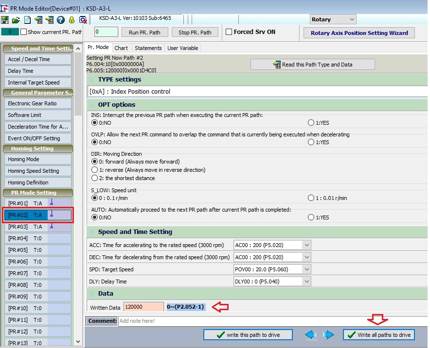
Click “Write all paths to drive” to complete the settings.
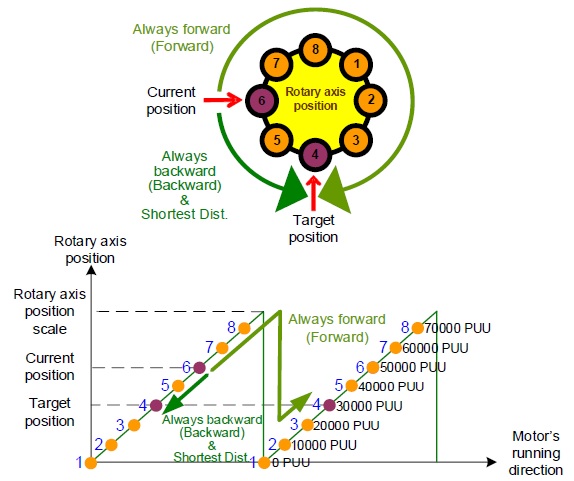
When “the shortest distance” is used
– With the shortest distance movement command, the motor rotates in the direction with the smallest amount of movement in the forward and reverse directions.
– In the case of a 180 degree opposite movement command, the rotation direction is determined by the polarity (+ or -?) of the calculation result of [travel amount] = [target position] – [current position].
– For example, if you move from 4 (30000 PUU) to 8 (70000 PUU) in the figure below,
[Movement amount] = 70000 (target value) – 30000 (current position) = +40000, and the polarity is +, so it moves in the forward direction.
– When moving in the opposite direction, from position 8 to position 4, the polarity is -40000 (minus), so it moves in the opposite direction.
* Please note that the position of 1 in the diagram below should be considered as 0 (zero). It’s not “position 80000”.
* If you continue to rotate forward, the feedback PUU will accumulate and become a large number, but the idea is the same.
* The idea is the same even if the direction is reversed and the feedback PUU is set to a “negative value”.
Notes
– If you rotate in the same direction, PUU will continue to increase (or decrease).
– If the coordinate system continues to rotate in the same direction and overflow is expected, set P2.070 Bit2 to “1”.
– AL235 (PR command overflow) will not be detected by masking the overflow above.
– When using with an absolute system, set the non-overflow setting of “P2.069 Z: function of preventing rotary axis position loss when overflow occurs” to “1”.
– Also, set “P2.070 Bit2: Overflow warning setting” to “1”.
Inquiry
Click here for inquiries by email